Pokémon mini Development Documentation
Input / Output
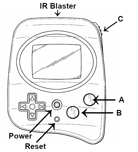
The PM has 10 dedicated input ports and 8 configurable I/O pins. For other pins which are considered I/O or dedicated output pins, see here
The reset button is not a general purpose input, though it is an input pin to the CPU it is also an input to other parts of the hardware, likely powering off other systems directly.
Dedicated inputs
| Port | Description | Interrupts | Registers |
|---|---|---|---|
| K00 | C button | → | → |
| K01 | B button | → | → |
| K02 | A button | → | → |
| K03 | Up button | → | → |
| K04 | Down button | → | → |
| K05 | Left button | → | → |
| K06 | Right button | → | → |
| K07 | Power button | → | → |
| K10 | Cart input | → | → |
| K11 | Cart detect | → | → |
Input button
Every keypad input except power and reset work the same way. They have interrupts available but largely they’re never used.
MINLIB offers a method for fetching the current input every frame, reproduced here. This allows software to call this method once per main loop (since it also performs a vsync) and check RAM for keys that are currently being pressed. Many commercial games implement their own versions of this, regardless of its existence in MINLIB.
It’s probably (TODO) possible to configure de-jitter for the interrupts as well as configure which edge they fire on. If you want to use these but still poll inputs, do not enable the interrupts for K0x, and use code something like this in your main loop:
	LD A, [BR:29h]     ; read current keymap IRQ state
	LD [BR:29h], 0FFh  ; clear IRQ state
	; Newly pressed (or released) keys as 1s in A
See also: interrupts A B C up down left right, registers A B C up down left right
Power button
The power button is the only keypad input which has a unique code path for the interrupt handler. It can be used as an extra button in the same way as any other button, so long as the console is on. However if the console has been put to sleep, it follows a unique wake-up routine.
Homebrew games, such as the hello world example, often just hook up the power IRQ handler to directly shut the console down. Commercial games tend to not define a handler (some do), and instead rely on polling it, either directly or in the same way as other inputs.
See also: interrupt, registers
Cartridge input
This input is a cartridge-defined input, essentially. A cartridge can decide what it means. It can be polled or handled by interrupt.
No commercial game uses this pin for anything. The PM2040 has this pin connected such that it could be driven to do something with custom firmware, but no existing firmware drives it for any purpose.
The DITTO mini, PokMini, PokeCard 512, and Leon·DIY do not have any trace to this pin. Unconfirmed for other flash carts.
See also: interrupt, registers
Cartridge detect
By default this interrupt is configured to fire when the cartridge is ejected. This is what the BIOS expects, so there isn’t a dedicated vector for it on the cartridge which the BIOS jumps to. However, software can still handle this.
To handle ejection, copy a handler method to RAM then write a JRL to it at $1FFD, and sleep the console (either 44h or 46h).
To handle insertion, set KCP11 to 1 and set up a handler in RAM same as before.
; Any calls or jumps to outside what was copied won't work.
COPY_TO_RAM MACRO start, end
	LD IY, #start
^loop:
	LD [IX], IY
	INC IX
	INC IY
	CP IY, #end
	JRS C, ^loop
ENDM

prepare_eject:
	; Copy both handlers to RAM
	LD IX, #CartEjectHandlerRAM
	COPY_TO_RAM cart_eject_handler, ceh__end
	LD IX, #CartInsertHandlerRAM
	COPY_TO_RAM cart_insert_handler, cih__end

	; write the JRL
	LD SP, #2000h
	LD BA, #(CartEjectHandlerRAM - 1FFDh + 1)
	PUSH BA              ; write the address for the JRL
	LD A, #0F3h          ; JRL opcode
	PUSH A               ; push it

	OR [BR:24h], #02h    ; enable interrupt
	OR [BR:21h], #30h    ; set priority to 3
	OR [BR:01h], #80h    ; avoid console shutdown on eject
	; draw some info to the screen, then:
	INT [46h]            ; sleep with display on

cart_eject_handler:
	LD [BR:28h], #02h    ; clear factor flag

	; we use the insert interrupt as an example
	; you could poll K11D instead or do something else entirely
	OR [BR:51h], #02h    ; KCP11 = 1, to detect insert

	; write the JRL
	LD SP, #2000h
	LD BA, #(CartInsertHandlerRAM - 1FFDh + 1)
	PUSH BA              ; write the address for the JRL
	LD A, #0F3h          ; JRL opcode
	PUSH A               ; push it

	; do what you want!
ceh__loop:
	; but remember there's no returning to software!!
	JRS ceh__loop
ceh__end:

cart_insert_handler:
	LD [BR:28h], #02h    ; clear factor flag
	AND [BR:51h], #~02h  ; KCP11 = 0, to detect eject
	AND [BR:01h], #~80h  ; allow console to shutdown if ejected again
	LD SP, #2000h        ; software can overwrite the JRL we had here now
	; do what you want!
	; if you're going to re-enter software somewhere, jump
cih__end:
See also: interrupt, registers
I/O ports
| Port | I/O | Description | Interrupts | Registers |
|---|---|---|---|---|
| P00 | I/o | IR receiver | → | → |
| P01 | i/O | IR transmitter | - | → |
| P02 | I/O | EEPROM data | - | → |
| P03 | I/O | EEPROM clock | - | → |
| P04 | O | Rumble motor | - | → |
| P05 | i/O | IR disable | - | → |
| P06 | I/o | Shock sensor | → | → |
| P07 | ? | ? | - | - |
I/O ports (or P ports) are ports which can be configured to act either as input or output by the software. Not all ports on the PM may be used as both. In the above table’s I/O column, upper-case indicates the mode is intended, lower-case indicates it’s possible but not intended.
Configure a port with its respective IOC register. A value of 0 configures it as input, a value of 1 configures it as output.
| IOC=0 | IOC=1 | |
|---|---|---|
| Read D | Input data* | Last written? |
| Write D | ??? | Output data |
* If there is no data being externally driven on the pin, the state is left undetermined as that bit is defined as floating.
During initialization the BIOS configures P01 (IR TxD), P04 (Rumble), and P05 (IR disable) as output ports, and everything else as input here.
Although switching the EEPROM clock to input is used normally, it’s used to disable clocking to the EEPROM and does not expect to actually receive signal.
Previous documentation suggested that P07 may also be an IR transmission pin: (IR Transmitter? Used to double power?) but this is unconfirmed.
Rumble
Write a 1 to P04D to start the rumble motor, write a 0 to turn it off.
The recommended way to rumble for a certain amount of time would be to have a method that checks if rumble is desired, starts rumbling, then writes a value to RAM representing the number of frames it should rumble for. Then in your main loop/vsync, decrement that value by 1, and if it reaches 0, disable rumble.
// rumble.h
void start_rumble(char frames);
void step_rumble(void);

_inline void stop_rumble(void) {
	IO_DATA &= ~0x10;
}

// rumble.c
#include <pm.h>
#include "rumble.h"

char rumble_frames = 0;

void start_rumble(char frames) {
	IO_DATA |= 0x10;
	rumble_frames = frames;
}

void step_rumble(void) {
	if (rumble_frames > 0 && !rumble_frames--) {
		stop_rumble();
	}
}

// main.c
#include <pm.h>
#include "rumble.h"

int main(void) {
	// ...setup...
	for (;;) {
		// ...
		wait_vsync();
		step_rumble();
	}
}
See also: registers
Shock
When the player shakes the console, P06D goes low and the shock sensor interrupt triggers. It’s possible to poll P06D but it’s not recommended. For polling, poll FP6 instead.
int main(void) {
	// ...setup...
	IRQ_ENA4 &= ~IRQ4_SHOCK;  // this is the default, disabled

	for (;;) {
		// ...
		wait_vsync();
		if (IRQ_ACT4 & IRQ4_SHOCK) {
			IRQ_ACT4 = IRQ4_SHOCK;
			// handle shock
		}
	}
}